Introduction
Often, you need your device to perform some actions based on user action. A very simple use case can be performing a reset. You provide a reset button on your device, and whenever that button is pressed, the device resets itself. Other examples can be switching between ‘setup’ mode and ‘normal mode’. On pressing a button, the device goes into the setup state where the user can configure its settings, and on pressing it again, the device switches back to the normal mode. These are just some examples. I’m sure you can come up with more examples yourself.
The main capability required to address all the above use cases is the recognition of button interrupts by your device’s microcontroller. So in this article, let’s look at how we can detect and take action based on button interrupts to ESP32. This is going to be much simpler than timer interrupts that we discussed in an earlier article.
Note that by buttons, we are referring to button switches. When the button is pressed, the switch is closed. Otherwise, the switch is open.
Configuration
Button interrupts are technically referred to as external interrupts. Luckily for us, any GPIO of the ESP32 can accept external interrupts (unlike other boards like Arduino Uno, which can accept external interrupts on only some specific pins). We will configure pin 5 of the ESP32 to accept external interrupts here. You can choose any other GPIO pin as well.
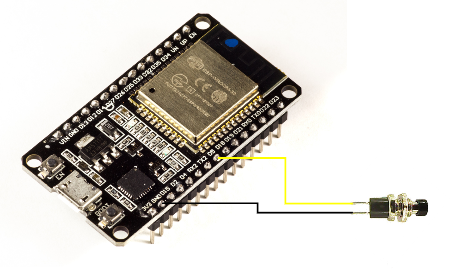
We will configure the pin as an input pullup, and connect the button switch between this pin and the ground. Thus, when the switch is open, this pin will be in the HIGH state, whereas it will be in the LOW state when the button is pressed. We will then configure the TESP32 to trigger an interrupt on the falling edge (HIGH to LOW), to detect the button press activity.
Circuit Diagram
The circuit diagram is quite straightforward. You just connect the button interrupt between pin 5 and GND. In general, we would have needed the pull up resistor on pin 5. But that will be handled internally by ESP32, once we configure the pin to the INPUT_PULLUP state.
Code Walkthrough
The code can be found on GitHub here.
Let’s begin the walkthrough.
We begin by specifying a couple of variables, for pin number and interrupt count.
const int interruptPin = 5;
volatile int interruptOccurrences = 0;
int nInterrupts = 0;
Note the volatile keyword before the interruptCounter declaration. It indicates that this variable can be modified within an interrupt service routine, or the function which gets executed when the interrupt is triggered. Without making this variable volatile, the variable won’t change its value within the interrupt function.
Next, a variable of type portMUX_TYPE is declared. This helps synchronize between the main code and the interrupt service routine. The variable is initialized with the portMUX_INITIALIZER_UNLOCKED value. We will see its usage in the later sections of the code.
portMUX_TYPE mux = portMUX_INITIALIZER_UNLOCKED;Next, the interrupt function is defined. This function is called every time the interrupt is triggered. The function is very simple. We simply increment the interruptOccurrences variable. Notice that line incrementing the variable is sandwiched between portENTER_CRITICAL_ISR(&mux) and portEXIT_CRITICAL_ISR(&mux). This is where the mux variable defined earlier comes into use.
void IRAM_ATTR handleButtonInterrupt() {
  portENTER_CRITICAL_ISR(&mux);
  interruptOccurrences++;
  portEXIT_CRITICAL_ISR(&mux);
}
What portENTER_CRITICAL_ISR does is, in very layperson terms, tell the ESP32 that a critical section has been entered. Therefore, any other section of the code, which wants to enter a critical section, using the same mux variable, should wait till this part exits (using portEXIT_CRITICAL_ISR). This is done to ensure that the variable doesn’t get modified in the main code and the interrupt at the same time. We will come back to this in the discussion of the loop code.
You may be wondering what the IRAM_ATTR tag means. It tells the ESP32 that this piece of code needs to be placed in the internal RAM of ESP32. This will make it much faster (RAM is much faster than Flash). ESP32 documentation states that the Interrupt Service Routines (ISRs) should have the IRAM_ATTR tag.
Also, note how lightweight the interrupt function has been kept. It is a good practice to exit the interrupt as soon as possible. All heavy calculations should be within the loop, and not the interrupt.
Next, in the setup part, we configure the pin to the INPUT_PULLUP mode, and attach the interrupt to the pin, on the falling edge.
void setup() {
Serial.begin(115200);
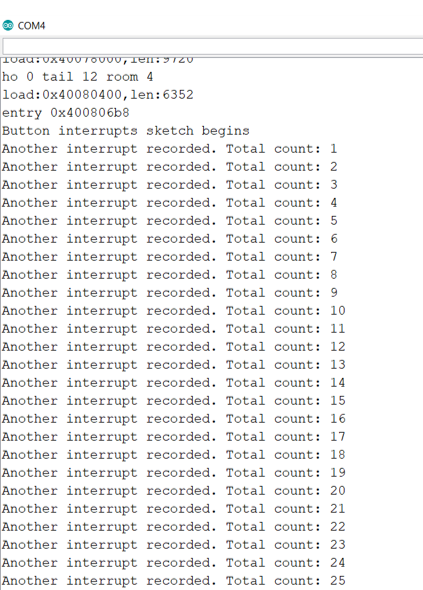
Serial.println("Button interrupts sketch begins");
pinMode(interruptPin, INPUT_PULLUP);
attachInterrupt(digitalPinToInterrupt(interruptPin), handleButtonInterrupt, FALLING);
}In the loop, we continuously check if a button interrupt has occurred. If it has, we first set the value of interruptOccurrences to 0 so that the next interrupt can be correctly recorded. We do this within the portENTER_CRITICAL and portEXIT_CRITICAL block, using the same mux variable. This makes sure that the ISR doesn’t modify the variable while it is being modified in the loop. Next, we increment the nInterrupts counter, and print to the serial monitor.
void loop() {

  if(interruptOccurrences>0){

      portENTER_CRITICAL(&mux);
      interruptOccurrences = 0;
      portEXIT_CRITICAL(&mux);

      nInterrupts++;
      Serial.print("Another interrupt recorded. Total count: ");
      Serial.println(nInterrupts);
  }
}
Serial Monitor Output
Here’s how the Serial Monitor output looks like:
I hope you liked this tutorial. To this basic code, you can add a lot more functionality. You can define actions when button is pressed twice, or thrice, and so on. Happy exploration!
For more tutorials on ESP32, checkout https://iotespresso.com/category/esp32/
Also, you may find this course on ESP32 on Udemy to be quite helpful. Do check it out.
Hi sir,
I wander why LEDs indication was not mentioned in code and explanation?
That’s because LEDs would mean additional circuit components. And they weren’t central to the topic of the post. Serial Monitor was sufficient for displaying the output.