Learn how to configure and use ESP32 Timer Interrupts to gather data at a fixed frequency
Introduction
Suppose you need to collect data from a sensor (analog or digital) at a fixed frequency for, say, FFT calculations. For the purpose of discussion, let us assume that we need to collect analog readings from a sensor on ESP32. Now, generally, the analogRead() execution time on ESP32 is in the ballpark of 10 microseconds. If the desired data collection interval is much larger than this value, say 1 second, then you may simply introduce a delay of 1 second in your loop, and you’ll get a collection interval of 1.00001 seconds, which will hardly affect your calculations.
However, if your desired collection frequency is, say, 1 millisecond, then introducing a delay will cause the collection to happen every 1.01 millisecond, an error of 1%. As you move closer to the 10-microsecond value, your error percentage increases.
What can be done to avoid this problem? Come in timers!
Every microcontroller has some timers which are generally built exactly for applications like these. A timer is essentially a counter. Let’s take a simple example. If you are given a counter which can count from 0 to 10, and you are given an interrupt every time it reaches the end of count, or overflows, then, just by adjusting the frequency of the count, you can get accurate time intervals. By setting the frequency to 1 Hz, you can accurately measure 10 seconds. Similarly, by setting the frequency to 100 Hz, you can accurately measure 0.1 seconds, or 100 milliseconds. Say you want to measure 5 seconds, but 2 Hz frequency is not available? Then just count from 5 to 10 instead of 0 to 10.
Timers work just like it was described in the example. Instead of 0 to 10, they count from 0 to (2^N -1), N being the number of bits of the counter. Thus, an 8-bit counter will count from 0 to 255, a 16-bit counter will count from 0 to 65535, and so on.
ESP32 has two timer groups, each group containing two 64-bit timers. Thus, there are four 64-bit timers in total.
These timers come with 16-bit pre-scalers. What are pre-scalers? They help divide the base clock frequency. ESP32 generally has a base clock frequency of 80 MHz. This can be a bit too high. Having a 16-bit pre-scaler means that you can divide the base clock frequency by at least 2 and by as much as 65536. 80 MHz/65535 = 1.22 KHz. Now, this means that the frequency of a timer can be adjusted from 1.22 KHz to 80 MHz (of course in discrete steps). This wide range of frequency, along with the fact that these are 64-bit timers ensures that almost any interval is possible with ESP32 timers.
Code Walkthrough
Enough theory! Now let’s get practical. We will consider a simple example of reading analog values at a fixed frequency on ESP32. Let’s walk through the code.
The code can be found on GitHub here: https://github.com/yash-sanghvi/ESP32/blob/master/Timer_Interrupts_ESP32/Timer_Interrupts_ESP32.ino
We begin with the definition of some variables:
int t1 = 0;
int t2 = 0;
int adc_read_counter = 0;
int SamplingRate = 1000; //Read 1000 values in one second.

hw_timer_t * timer = NULL;
volatile bool interruptbool1 = false;
Note that we’ve declared some integers, whose use will be clear in the setup and loop parts of the code. Next, we’ve declared the Sampling Rate in Hz. This variable indicates how many data points we want to read in one second. You can play around with this when you experiment. The timer has been declared as a pointer of type hw_time_t and it is initialized as a NULL pointer. Finally, a volatile bool has been defined. The volatile keyword indicates that we intend to modify this variable within an interrupt.
Next, we have declared the interrupt function. We don’t do much in that function, we just set the value of the bool to true.
/*Interrupt routine for Timer overflow event*/
void IRAM_ATTR onTimer() {
   interruptbool1 = true; //Indicates that the interrupt has been entered since the last time its value was changed to false
}
Because onTimer is an interrupt function, it can neither take in any arguments, nor return anything. You maybe curious about the ‘IRAM_ATTR’ part. What this tells the ESP32 is that this piece of code needs to be placed in the internal RAM of ESP32. This will make it much faster (RAM is much faster than Flash). ESP32 documentation states that the Interrupt Service Routines (ISRs) should have the IRAM_ATTR tag.
Next, we come to the setup part:
void setup() {
  Serial.begin(115200);
  timer = timerBegin(0, 80, true);                //Begin timer with 1 MHz frequency (80MHz/80)

  timerAttachInterrupt(timer, &onTimer, true);   //Attach the interrupt to Timer1

  unsigned int timerFactor = 1000000/SamplingRate; //Calculate the time interval between two readings, or more accurately, the number of cycles between two readings

  timerAlarmWrite(timer, timerFactor, true);      //Initialize the timer

  timerAlarmEnable(timer);
}
As you can see, we initialize Serial. Now pay attention to the next 5 lines of code.
Remember, the NULL pointer of type hw_timer_t that we defined earlier? It is assigned a value using timerBegin(0,80,true). The first argument, 0, states that we are using Timer0 of ESP32 (ESP32 has 4 timers: 0,1,2,3). The second argument defines the pre-scaler. Now, the base clock frequency of ESP32 is generally 80 MHz. We divide that by 80, to generate a nicer number: 1 MHz. Thus, timer 0 will count at a frequency of 1 MHz. The third argument, true, suggests that ESP32 should count up. If set to false, it would mean ESP32 should count down.
Next, we attach the onTimer function as an interrupt to our timer, using the timerAttachInterrupt function. While the first two arguments of the function are self-explanatory, the third one, true, indicates that we want the interrupt to be edge-type interrupt (meaning it should be triggered on an edge, rising/falling).
We next determine the timerFactor. Since our frequency is 1 MHz, we know the timer is going to count 1,000,000 values in 1 second. We want to read 1000 readings in every second. Therefore, we want to generate the interrupt every time the counter counts to 1,000,000/1000 = 1000. This is what we calculate and store in the timerFactor variable.
We use this variable in the timerAlarmWrite function, specifying that an alarm should be triggered every time the timer count reaches 1000. The third argument of this function, true, indicates that the timer should auto-reload. It means that after generating an alarm once, it should auto-reload and start counting again from 0 to 1000.
Finally, we enable the Alarm using timerAlarmEnable.
To summarize, we create the timer using timerBegin(), we attach the interrupt function, or the function to be executed everytime the timer hits an alarm, using timerAttachInterrupt(), we configure the alarm using timerAlarmWrite() and we enable the alarm using timerAlarmEnable().
In the loop, we check for the interruptbool1 variable constantly. If it is true, it means the alarm has been triggered, and we can read the analog values. We’ve added some print statements to log the time it takes to read 1000 readings.
void loop() {
  // put your main code here, to run repeatedly:
  if(interruptbool1){
      analogRead(36);
      interruptbool1 = false;
      if(adc_read_counter == 1){
          t1 = millis();
        }
      if(adc_read_counter == 1001){
          t2 = millis();
          Serial.println();
          Serial.print("Time taken to read 1000 readings is "); Serial.print(t2-t1);Serial.println(" milliseconds");
          Serial.println();
          adc_read_counter = 0;
        }
      adc_read_counter++;
    }
}
Results
Once you burn this code to your ESP32, and see the outputs on the Serial Monitor, you should see something like this:
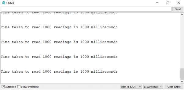
Go ahead and play around with the sampling rate variable, and try to determine the value at which the loop time exceeds the time interval between two alarms.
We hope you liked this post. For more tutorials on ESP32, check out https://iotespresso.com/category/esp32/. Specifically, you can check out the following posts:
- Create Custom WatchDog Timer in ESP32: Learn about the concept of watchdog timers and extend the concept of timer interrupts to create your custom watchdog timer on ESP32.
- Button (external) interrupts with ESP32: Want ESP32 to take a specific action on the press of a button? Learn how to configure button interrupts on ESP32.
Also, you may find this course on ESP32 on Udemy to be quite helpful. Do check it out.
hey, i’m from brazil, i would like to create a 3 minute routine. Every 3 minutes it returns a value for a variable. It’s possible?
Yes, it is definitely possible, considering that ESP32 has 64-bit counters, meaning they can count up to 1.8446744e+19. You can set the sampling rate as 1/180 in the code given in the post. Alternatively, you can set the timer factor directly to 180*1000000.
unsigned int timerFactor = 1000000*180;I was curious if you ever thought of changing the layout of your site?
Its very well written; I love what youve got to say. But maybe
you could a little more in the way of content so people could connect with it better.
Youve got an awful lot of text for only having one
or two images. Maybe you could space it out better?
Hey, first off great job here! Was a great read. I just wanted to know whether I could achieve the following with the ESP32/ESP8266:
1. Timer1 is running, ESP in deep sleep, after 2 hours Timer1 reaches desired counter value, ESP wake up and turns on a pin
2. When woken up Timer2 is triggered to start, lasts for about an hour
3. Once Timer2 is done, ESP back to deep sleep (pin LOW) and Timer1 restarts
I’m mainly having trouble understanding how to choose a prescaler for these huge intervals (can’t seem to work it out).
Would love your feedback on this! Thanks once again!
Hello Hadi,
In your case, you want the Timer1 interrupt to be triggered in 2 hours (7200 seconds) after it is set, and Timer2 interrupt in 1 hour (3600 seconds). Therefore, I’d advise a high value of a prescalar. In the article, I’ve set the prescalar to 80. That way, the timer was counting to 1M in 1 second. The prescalars are 16-bit. So the max value is 65536 (2^16). To keep the numbers nice, let’s choose a prescalar of 40,000. Thus, the timer will count 2000 values in 1 second. Now, since timer1 needs to be triggered in 2 hours, its timerFactor will be 2000*7200 = 14,400,000. Similarly, the timerFactor of timer1 will be 2000*3600 = 7,200,000. I hope this helps. Let me know if any part is not clear.