Introduction
We have seen how to create a timer interrupt in ESP32. In this tutorial, we will see how to use the concept of timer interrupts to create your custom watchdog timer in ESP32.
Prerequisites
It is highly recommended that you go through the Timer Interrupts with ESP32 tutorial, before starting this one. It covers both the theory behind timers, and the code-level explanation of timer interrupts. In this tutorial, it will be assumed that you are comfortable with timer interrupts on ESP32.
About Watchdog Timer
If you don’t know what a watchdog timer is, it is a fail-safe introduced in the system to recover from malfunctions. Very crudely, if your code gets stuck somewhere, the watchdog timer will get triggered, and it will reboot the device. In the absence of the watchdog timer, the device will stay stuck forever, till there is a power reset.
Thus, the watchdog is essentially a timer interrupt, which reboots the device if it gets triggered. During normal functioning, the code will try its best to not let the watchdog timer get triggered. How does it do that? By periodically resetting the count. This is often referred to as either ‘kicking the dog’ or ‘feeding the dog’. You may as well call it ‘petting the dog’, to keep it from barking (interrupt trigger) :P.
If the code gets stuck, it will fail to reset the count, the interrupt will get triggered, and the device will reboot. The watchdog is a blessing, especially when you have deployed your devices remotely and it gets stuck and there is no way of figuring out what went wrong, and how to recover the device.
Code Walkthrough
The code can be found on GitHub here: Arduino sketch.
It is quite straightforward, especially if you have gone through the timer interrupts tutorial.
We begin with the definition of the watchdog timeout value, in seconds, and the null pointer which we will eventually use as the timer.
#define WATCHDOG_TIMEOUT_S 3

hw_timer_t * watchDogTimer = NULL;
Since we have defined the timeout value to be 3, if the code does not feed the watchdog for 3 seconds, the device will reboot. You can change the value of the timeout according to your requirements.
Next, we define the interrupt function
void IRAM_ATTR watchDogInterrupt() {
  Serial.println("reboot");
  ESP.restart();
}
As you can see, we simply print “reboot” within the interrupt, to indicate that we are within the interrupt function, and then restart the ESP32.
Next, we define a function to feed the watchdog. This function should be called regularly within the code, in gaps less than 3 seconds.
void watchDogRefresh()
{
  timerWrite(watchDogTimer, 0);                    //reset timer (feed watchdog)
}
As you can see, all this function does is reset the counter of watchDogTimer, so that it has to start counting again. Thus, its 3 seconds counting interval begins afresh every time this function is called.
Within the setup, we simply initialize Serial, and set up our timer, using timer 2 of ESP32. Please refer to the prerequisite article for understanding the timer setup part.
void setup() {
  // put your setup code here, to run once:
  Serial.begin(115200);
  Serial.println("Watchdog sketch start");

  watchDogTimer = timerBegin(2, 80, true);
  timerAttachInterrupt(watchDogTimer, &watchDogInterrupt, true);
  timerAlarmWrite(watchDogTimer, WATCHDOG_TIMEOUT_S * 1000000, false);
  timerAlarmEnable(watchDogTimer);

}
Within the loop, we demonstrate how the failure to feed the watchdog for more than 3 seconds leads to a system reboot.
void loop() {
  // put your main code here, to run repeatedly:
  delay(1000);
  Serial.println("Watchdog not triggered in 1 second. Feeding it...");
  watchDogRefresh();

  delay(2000);
  Serial.println("Watchdog not triggered in 2 seconds. Feeding it...");
  watchDogRefresh();

  delay(4000);
  Serial.println("Watchdog not triggered in 4 second. Feeding it..."); //This shouldn't get printed
  watchDogRefresh();
}
Serial Monitor Output
The Serial Monitor output looks like the following:
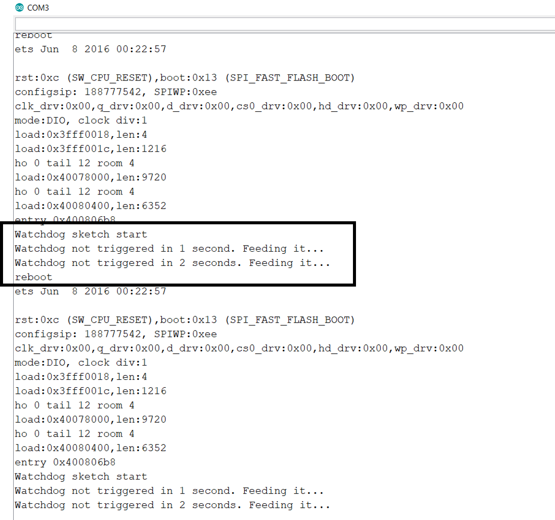
As you can see, the line after the 4-second delay did not get printed. This is because the watchdog timer interrupt got triggered before that and reset the device.
That’s it. Hope you found this tutorial helpful.
For more tutorials on ESP32, check out https://iotespresso.com/category/esp32/. Also, you may find this course on ESP32 on Udemy to be quite helpful. Do check it out.
1 comment