If you’ve worked with I2C (or Wire as referred to by Arduino), then you would know that I2C has the capability of working with 128 peripherals at a time. The only condition is that all the peripherals should have a distinct address.
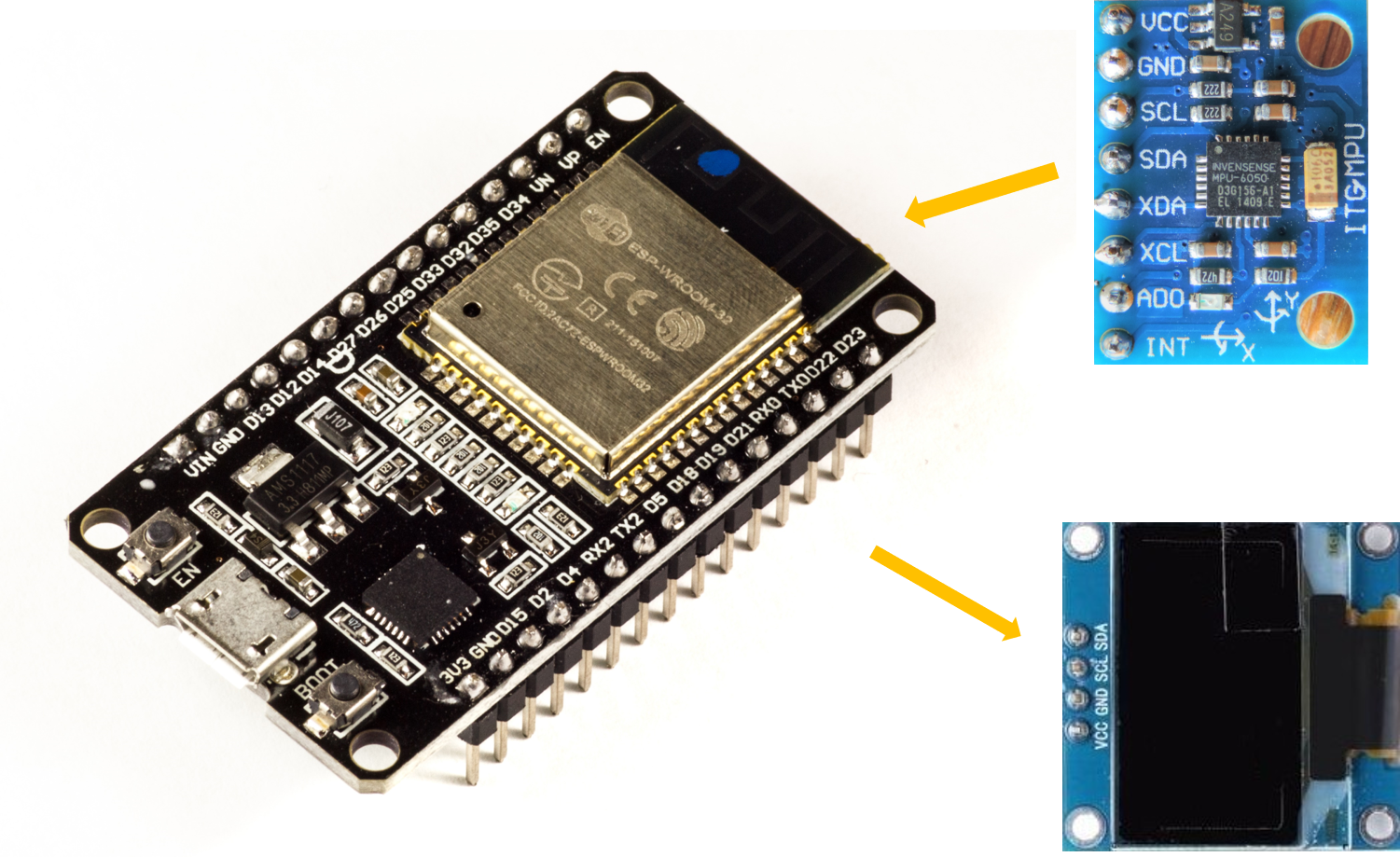
In this tutorial, we will understand how to work with two I2C peripherals simultaneously connected to ESP32. We will use MPU6050 (a 6-axis accelerometer+gyroscope MEMS sensor) and OLED display as the peripherals. But you could use any peripherals having distinct addresses.
Required Libraries
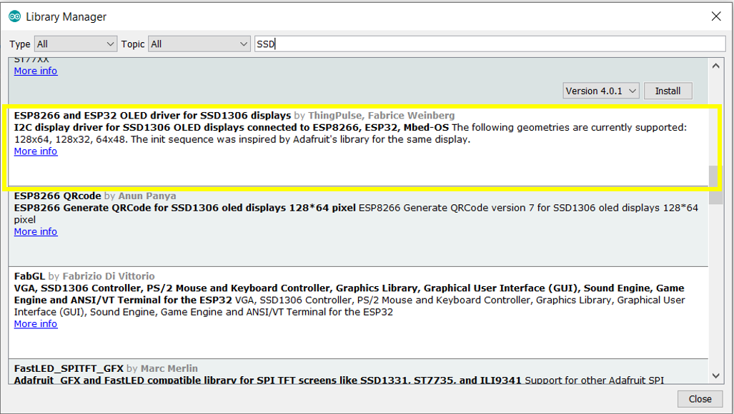
For working with MPU6050, you don’t need any library apart from the built-in Wire library. For working with OLED Display, we will use this library developed by ThingPulse. It can also be downloaded from the Library Manager.
Circuit Diagram
The circuit diagram is shown below.
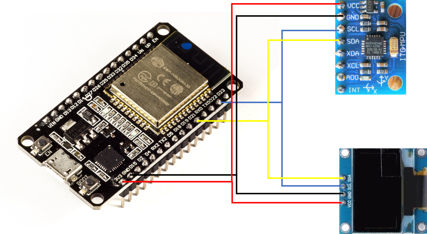
As you can see, the Vcc pin of both MPU6050 and the OLED Display is connected to the 3V3 pin of ESP32, GND to GND, SDA to pin 21 of ESP32 and SCL to pin 22 of ESP32.
Code Walkthrough
We will read acceleration data from MPU6050 and print it on the OLED screen. The code can be found on GitHub here.
Let’s begin the walkthrough.
We begin with the inclusion of the required libraries:
#include "SSD1306.h"
#include<Wire.h>
Later, we add OLED and MPU specific variables:
//OLED related variables
#define OLED_ADDR   0x3c
#define OLED_SDA    21
#define OLED_SCL    22

//MPU6050 related variables
#define MPU_ADDR 0x68  // I2C address of the MPU-6050
#define MPU_SDA 21
#define MPU_SCL 22
int16_t AcX, AcY, AcZ, Tmp, GyX, GyY, GyZ, AcX_H, AcX_L, AcX_2;
Note the two addresses. OLED display has an I2C address of 0x3c, while MPU6050 has an I2C address of 0x68. This makes it possible to use two of them simultaneously with ESP32. It is not possible to use two peripherals having the same I2C address simultaneously with ESP32.
Next, we create the object for our OLED display, and define a function to print messages on the OLED screen in 3 lines:
SSD1306  display(OLED_ADDR, OLED_SDA, OLED_SCL);


void showOLEDMessage(String line1, String line2, String line3)
{
  display.init();                                                           // clears screen
  display.setFont(ArialMT_Plain_16);
  display.drawString(0, 0, line1);                                          // adds to buffer
  display.drawString(0, 20, line2);
  display.drawString(0, 40, line3);
  display.display();                                                        // displays content in buffer
}
Note that we are using ArialMT_Plain font with a font size of 16 points. If this is too large for you, you can bring it down to 10 points.
As you can see from the function above, we have split the display screen into 3 lines, with the first one starting at (0,0), the next one starting at (0,20) and the last one starting at (0,60). You can adjust these parameters based on your requirements.
Within the setup, we initialize the MPU6050 (wake it up by writing 0 to the PWR_MGMT_1 register), and initialize Serial.
void setup() {
  // put your setup code here, to run once:
  Wire.begin(MPU_SDA, MPU_SCL, 100000); // sda, scl, freq
  Wire.beginTransmission(MPU_ADDR);
  Wire.write(0x6B);  // PWR_MGMT_1 register
  Wire.write(0);     // set to zero (wakes up the MPU-6050)
  Wire.endTransmission(true);

  Serial.begin(115200);
  Serial.println("Setup complete...");
}
Within the loop, we read 14 bytes from the MPU6050 starting from address 0x3B. As per the datasheet of MPU6050, the 14 bytes starting from 0x3B contain acceleration data for the 3 directions, followed by two bytes of temperature data, followed by gyroscopic data for the 3 directions. Each acceleration/ gyroscope value comprises of two bytes (lower and higher bytes), which are then concatenated together to report the final values.
The acceleration values out of these are then displayed on the OLED screen. They are also printed on the Serial Monitor, so that you can compare the OLED data with Serial Monitor data.
void loop() {
  // put your main code here, to run repeatedly:
  Wire.beginTransmission(MPU_ADDR);
  Wire.write(0x3B);  // starting with register 0x3B (ACCEL_XOUT_H)
  Wire.endTransmission(true);
  Wire.beginTransmission(MPU_ADDR);
  Wire.requestFrom(MPU_ADDR, 14, true); // request a total of 14 registers
  AcX = Wire.read() << 8 | Wire.read(); // 0x3B (ACCEL_XOUT_H) & 0x3C (ACCEL_XOUT_L)
  AcY = Wire.read() << 8 | Wire.read(); // 0x3D (ACCEL_YOUT_H) & 0x3E (ACCEL_YOUT_L)
  AcZ = Wire.read() << 8 | Wire.read(); // 0x3F (ACCEL_ZOUT_H) & 0x40 (ACCEL_ZOUT_L)
  Tmp = Wire.read() << 8 | Wire.read(); // 0x41 (TEMP_OUT_H) & 0x42 (TEMP_OUT_L)
  GyX = Wire.read() << 8 | Wire.read(); // 0x3B (ACCEL_XOUT_H) & 0x3C (ACCEL_XOUT_L)
  GyY = Wire.read() << 8 | Wire.read(); // 0x3D (ACCEL_YOUT_H) & 0x3E (ACCEL_YOUT_L)
  GyZ = Wire.read() << 8 | Wire.read(); // 0x3F (ACCEL_ZOUT_H) & 0x40 (ACCEL_ZOUT_L)


  //Serial.print("AcX = ");
  Serial.print(AcX); Serial.print(" , ");
  //Serial.print(" | AcY = ");
  Serial.print(AcY); Serial.print(" , ");
  // Serial.print(" | AcZ = ");
  Serial.print(AcZ);
  Serial.print(" , ");


  Serial.print(GyX); Serial.print(" , ");
  //Serial.print(" | AcY = ");
  Serial.print(GyY); Serial.print(" , ");
  // Serial.print(" | AcZ = ");
  Serial.print(GyZ); Serial.println(" , ");

  String AcclnX = "X: " + String(AcX) + ",";
  String AcclnY = "Y: " + String(AcY) + ",";
  String AcclnZ = "Z: " + String(AcZ);
  showOLEDMessage(AcclnX,AcclnY,AcclnZ);
  delay(100);

}
You may notice that we don’t have a Wire.endTransmission(true) command at the end of read. This is because the third argument of Wire.requestfrom(MPU_ADDR,14,true) indicates to the ESP32 to send a stop command after reading the required number of bytes. Had we passed false instead of true, ESP32 would have sent a restart command instead of a stop command.
The reason why the two peripherals work smoothly together is that communication happens with only one peripheral at a time. Only after the data has been obtained from MPU6050 and communication with that peripheral has ended, is the display initialized and messages are written to it.
Thus, you can see from this tutorial, how two peripherals connected to the exact same pins of ESP32, can share the I2C bus, because they have different addresses. If you liked this tutorial, you may also like other tutorials here.