Introduction
Arduino IoT Cloud is Arduino’s attempt to tap the growing IoT market. It offers integration with several Arduino IoT boards, and also some third-party boards like ESP8266 and ESP32. In this tutorial, we will see:
- How to create a ‘thing’ using ESP32 as the device
- How to generate the sketch for the thing, edit it, and program the board
- Visualize the data coming in from the board on a simple dashboard on Arduino IoT Cloud
The steps mentioned in this tutorial can be replicated for any other board as well.
Prerequisites
You should have an ESP32 board (or ESP8266 or one of the Arduino IoT boards). You should be familiar with basic Arduino programming.
Additionally, you should have created a free Arduino IoT Cloud Account. That’s pretty much it.
Part 1 – Create a Thing
What is a thing? It is an IoT node – an independent unit that will sense some physical quantity (temperature, humidity, etc.), and send the measurements to the Arduino IoT Cloud. Let’s create one.
Once you have created your free Arduino IoT Cloud Account, log in. You should be able to see a screen like the one below.
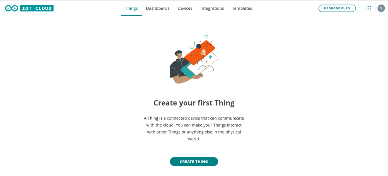
Click on the ‘CREATE THING’ button. You should see a screen similar to the one below:
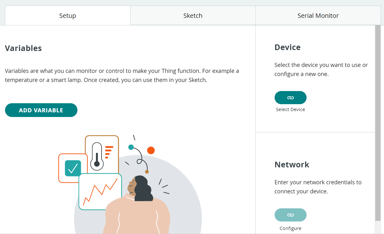
Set up the Device
Click on ‘Select Device’ button in the Device Section. A popup will open up, similar to the one shown below.
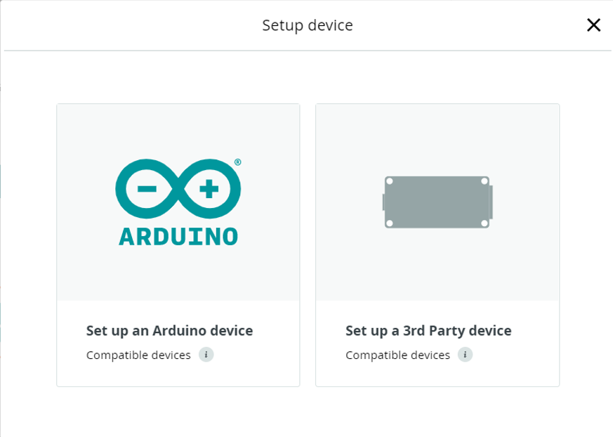
Click on ‘Set up a 3rd Party device’ and select ESP32, and select ESP32, and choose your board from the dropdown. I have the TTGO LoRa32-OLED V1 board. You can select the board available with you.
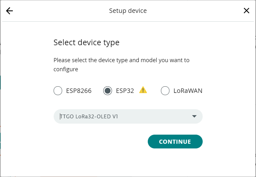
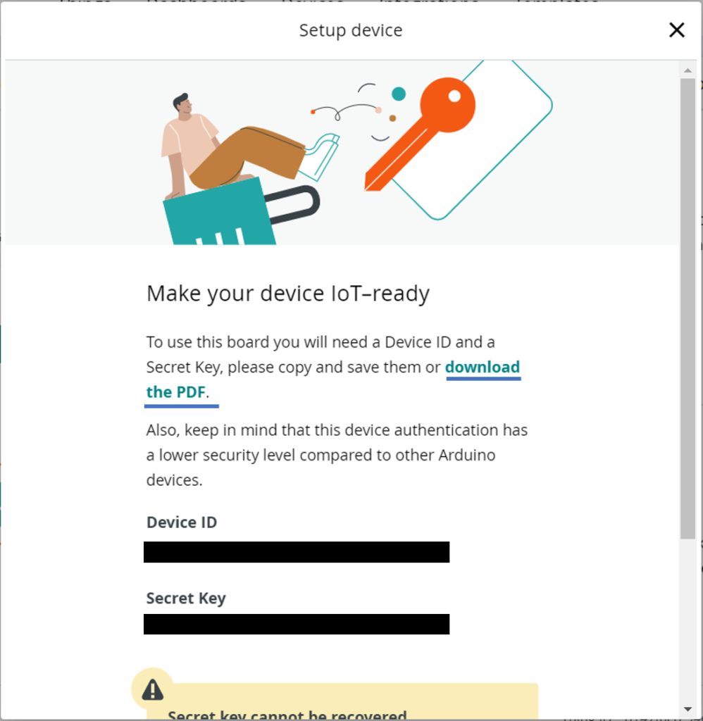
Click on ‘CONTINUE’, give your device a name and click on ‘NEXT’. The next screen that opens up is quite important. You are given the Device ID and SecretKey. The SecretKey is available only once. So please note it down. You can also use the ‘download PDF’ option that is shown in the popup. Once you have noted the SecretKey/ downloaded the PDF, tick the check box stating so, and click ‘CONTINUE’
With this, your device is set.
Configure Variables
What are variables? They correspond to the quantities being sensed. Every IoT device measures some physical quantity (temperature, humidity, location, heart rate, etc.), and sends the data to the server. On the Arduino IoT Cloud, these quantities of interest can be defined as variables. Defining variables is important as Arduino will do most of the work for us once the variables are generated, in the Auto-generated code. We’ll see that shortly.
Click on the ‘ADD VARIABLE’ button, and configure any variable that your ESP32 will measure. For now, I’ll set a variable named ‘temperature’ of type ‘Temperature Sensor (Celsius)’, mimicking the case when a temperature sensor is connected to the ESP32. It’ll be kept Read-only, i.e., the Cloud can only read the value of this variable from the device, and not send a new value to the device. I’ll configure the variable update policy such that the variable’s value will be sent to the Cloud whenever it changes by at least 1 degrees Celsius.
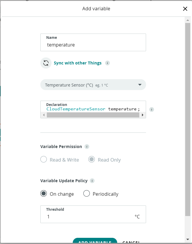
Once done, click on ‘ADD VARIABLE’. You can similarly add more variables. I’ll keep only one variable for now.
Configure Network
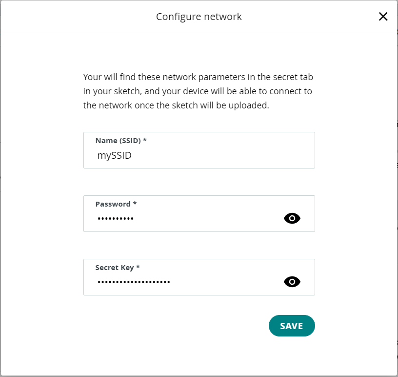
Click on the ‘Configure’ button in the ‘Network’ tile. A popup will show up, where you will be asked to enter the SSID and password of the network that your device will connect to. Enter these details. You will also be asked for the SecretKey, which you noted down in the ‘Set up the device’ step. Once these details are entered, click ‘SAVE’
That’s it. You have successfully configured your thing. Now let’s move on to the next part.
Part 2 – Program the board
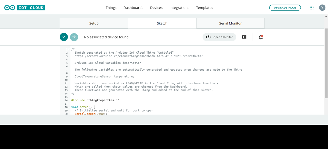
Move on to the ‘Sketch’ tab. You will see the auto-generated code in the text editor, along with the familiar ‘Verify’ and ‘Upload’ buttons.
Editing the Code
While you can edit the code on this screen itself, I personally prefer to use the Arduino Online Editor. Click on the ‘Open Full Editor’ button. That should open up a new tab, showing the code in Arduino Online Editor (you may be asked to re-login to the editor). You should be able to see a screen similar to the one below.

You will be able to see 3 files (apart from the ReadMe):
- The .ino file: This is the file wherein we can make edits. The comment //Your code here, in the loop indicates where we can start making edits.
- A thingsProperties.h file: This is an important file, that declares the variables that we configured earlier, the SSID, password, and SecretKey that we configured earlier, and also contains functions for initializing the Properties of the board (initProperties).
- Secret: This tab should be used only if you wish to make changes to the SSID, Password or the SecretKey configured earlier.
Now, we will make a small edit. In the loop, we will set the temperature to increase by 0.5 and reset to 0 if its value crosses 200. We will also introduce a 1-second delay in the loop. Ideally, the temperature should come in from a sensor, and you should make edits to the code to read values from the sensor.
void loop() {
  ArduinoCloud.update();
  // Your code here
  temperature = temperature+0.5;
  if(temperature > 200){
    temperature = 0;
  }
  delay(1000);
}
You can now hit the ‘Verify’ button to make sure that your sketch is getting compiled without any bugs.
Program the board
In order to program the board using the web browser, you will need to install the Arduino Create Agent. Click here and follow the steps to download and install the agent on your machine. Once you are done, you should be able to see the Arduino Create Agent Tray Icon. Also, the COM Port will be shown along with the board in the Arduino Online Editor. You may want to refresh once if the COM Port doesn’t show immediately, and you might have to click the dropdown and select the COM Port manually in case you have multiple peripherals connected.
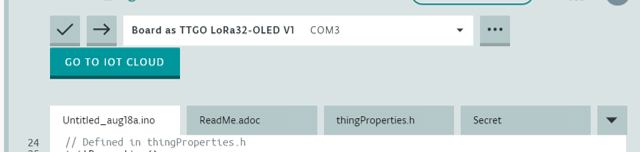
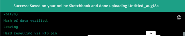
Now, you can click on the Upload button (->) and the sketch should start getting uploaded. You can check the status in the terminal at the bottom.
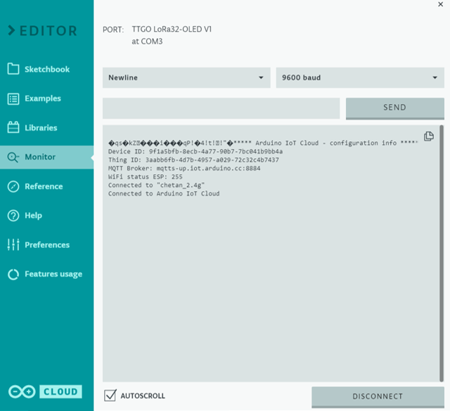
Next, you can click on the Serial Monitor from the left pane, to see the serial print statements.
Part 3 – Visualize the incoming data on a dashboard
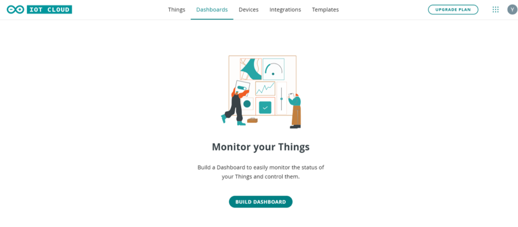
We will create a very simplistic dashboard here. Go to the Arduino IoT Cloud, and click on ‘Dashboards’ from the top menu, and click on ‘BUILD DASHBOARD’
Click on the Edit icon, then click on the ‘Add’ dropdown, go to the ‘Things’ pane, and select your thing.
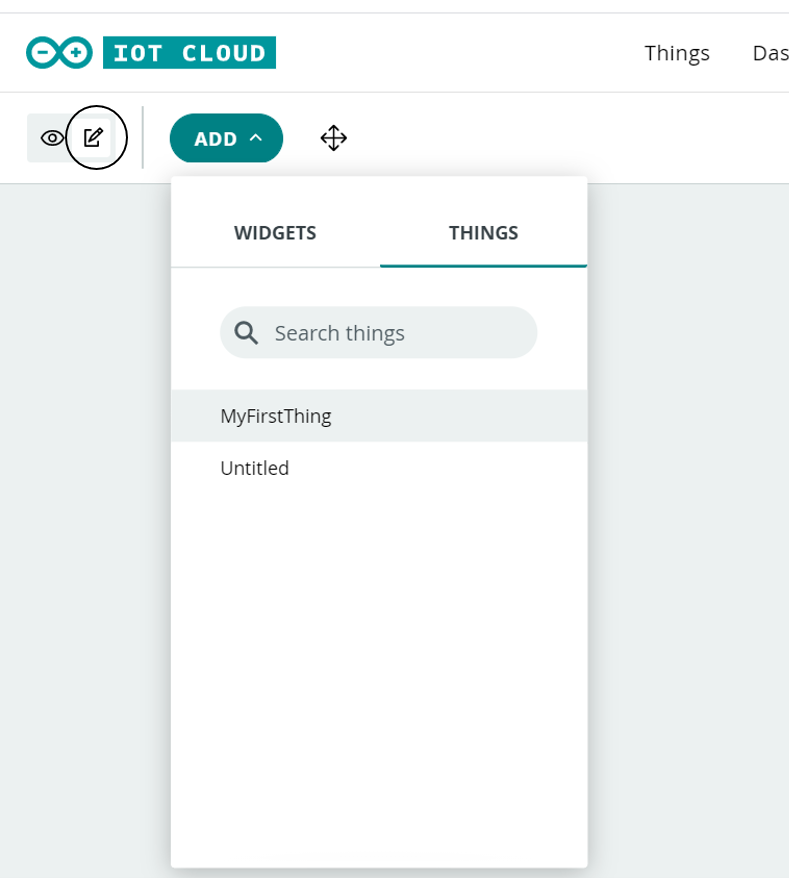
Click on ‘CREATE WIDGET’ in the popup that opens up, and you should start seeing the data getting updated realtime (provided your thing is powered ON).
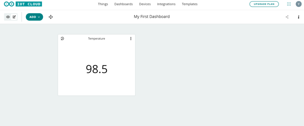
That’s it. Congratulations on successfully linking your ESP32 to the Arduino IoT Cloud, and displaying the data on a dashboard.
Since you are here, you may find this course on Udemy, which explains how to link ESP32 with AWS IoT, to be quite interesting. An introductory article on linking ESP32 to Arduino IoT Core can be found here.
Also, please check out other posts on ESP32 on check out further posts on iotespresso.com.
1 comment